some inspiration
A Hilbert Curve is a a continuous fractal space-filling curve first described by the German mathematician David Hilbert in 1891. It belongs to a family of space filling curves that create very distinct and interesting fractal patterns.
This particular project came to me by way of my coworker Angus who had printed a large copy of the curve. He inserted a small ball bearing which you could guide through the whole maze by tiling the part.
I designed a 2 DOF actuator using a single motor which rotated a ramped surface. A combination of pins and magnets keep the maze rotationally constrained - only allowing it to inherit the angle of the ramp.
You can check out the blog posts I made throughout the design process for more details on how it was developed:
make it yourself
This project is comprised of mostly 3D printed parts, but for electronics you’ll need an Arduino nano, a stepper driver, and a stepper motor. The complete BOM of printed parts, hardware, and electronics is listed below.
things to buy
1x Arduino Nano
1x Stepper Driver
1x NEMA 11 Stepper Motor
4x M3x25 Standoffs
1x Micro USB Adapter
4x 3mm Heatset Insert
4x M3x12 Socket Head Screws
4x M3x8 Socket Head Screws
2x 1/8” Diametric Magnets
2x M3x10 Dowel Pins
1x 4mm Ball Bearing
You’ll also want an assortment of wires and connectors to create the wire harnesses and protoboard as well as access to a solder iron and solder.
things to print
Files for these parts can be found on my thingiverse page here!
1x Hilbert Curve
1x Base
1x Fixed Pillar
1x Rotor
1x Drive Gear
1x Cover
putting it together
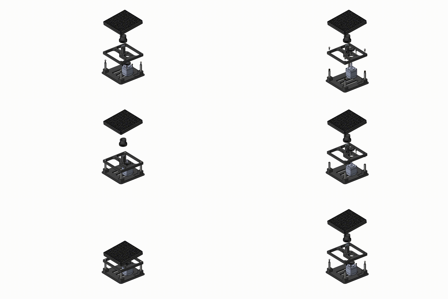
I did my best to make an assembly GIF to help guide where everything goes. The assembly is very straightforward - the one thing to be aware of is the orientation of the magnet. To press the magnet in the proper position, the magnets must be aligned when the low corner of the fractal is in the back left corner of the base where the Micro USB port is.
wiring
The wiring diagram for the protoboard can be found below.
software
I wrote the following code for the Nano which has a static solution matrix that feeds a move queue, which in turn, commands motor directions and distances.
#include "AccelStepper.h"

// AccelStepper Setup
AccelStepper stepperX(1, 6, 5);

// Stepper Travel Variables
float gearRatio = (20/25);
int fullRotation = (8*200*gearRatio);
int quarter = (fullRotation/4);
int plant = 1000;

//Soltuion array
  // 1 = Clockwise Rotation
  // 0 = Forward Movement
  //-1 = Counterclockwise Rotation

int solution[] = {
  1, 1, 1, 0, -1, -1, 0, 1, 0, -1, -1, 0, 1, 1, 0, -1,
  0, 1, 1, 0, -1, 0, 1, 1, 0, -1, -1, -1, 0, 1, 1, 0,
  -1, 0, 1, 1, 0, -1, 0, 1, 1, 0, -1, -1, 0, 1, 0, -1,
  -1, 0, 1, 0, -1, -1, 0, 1, 1, 0, -1, 0, 1, 1, 0, -1,
  -1, 0, 1, 0, -1, -1, 0, 1, 0, -1, -1, 0, 1, 1, 1, 0,
  -1, -1, 0, 1, 0, -1, -1, 0, 1, 0, -1, -1, 0, 1, 1, 0,
  -1, 0, 1, 1, 0, -1, 0, 1, 0, -1, 0, 1, 1, 0, -1, 0,
  1, 1, 0, -1, -1, 0, 1, 0, -1, -1, 0, 1, 0, -1, -1, 0,
  1, 1, 1, 0, -1, -1, 0, 1, 0, -1, -1, 0, 1, 0, -1, -1,
  0, 1, 1, 0, -1, 0, 1, 1, 0, -1, -1, 0, 1, 0, -1, -1,
  0, 1, 0, -1, -1, 0, 1, 1, 0, -1, 0, 1, 1, 0, -1, 0,
  1, 1, 0, -1, -1, -1, 0, 1, 1, 0, -1, 0, 1, 1, 0, -1,
  0, 1, 1, 0, -1, -1, 0, 1, 0, -1, -1, 0, 1, -1, -1, -1,
  0, 1, 1, 0, -1, 0, 1, 1, 0, -1, -1, 0, 1, 0, -1, -1,
  0, 1, 0, -1, -1, 0, 1, 1, 1, 0, -1, -1, 0, 1, 0, -1,
  -1, 0, 1, 0, -1, -1, 0, 1, 1, 0, -1, 0, 1, 1, 0, -1,
  0, 1, 1, 0, -1, -1, 0, 1, 0, -1, -1, 0, 1, 1, 0, -1,
  0, 1, 1, 0, -1, 0, 1, 1, 0, -1, -1, -1, 0, 1, 1, 0,
  -1, 0, 1, 1, 0, -1, 0, 1, 1, 0, -1, -1, 0, 1, 0, -1,
  -1, 0, 1, 0, -1, 0, 1, 0, -1, -1, 0, 1, 0, -1, -1, 0,
  1, 1, 0, -1, 0, 1, 1, 0, -1, 0, 1, 1, 0, -1, -1, -1,
  0, 1, 1, 0, -1, 0, 1, 1, 0, -1, 0, 1, 1, 0, -1, -1,
  0, 1, 0, -1, -1, 0, 1, 1, 0, -1, 0, 1, 1, 0, -1, 0,
  1, 1, 0, -1, -1, 0, 1, 0, -1, -1, 0, 1, 0, -1, -1, 0,
  1, 1, 1, 0, -1, -1, 0, 1, 0, -1, -1, 0, 1, 0, -1, -1,
  0, 1, 1, 0, -1, 0, 1, 1, 0, -1, };

int j;

void setup() {
   Serial.begin(9600);
   stepperX.setMaxSpeed(500);
   stepperX.setAcceleration(2500);
   stepperX.setCurrentPosition(0);
}

void loop() {
  for(int i = 0; i <= sizeof(solution); i++){         //move sequentially through the solution array
    runMove(solution[i])                              //pass next movement command to run move function
  }
}

int runMove(int j){
  if (j == -1){                                       //if next move is -1, run counterclockwise
    stepperX.move(quarter);
    while (stepperX.distanceToGo() != 0){             //run motor until you reach target
      stepperX.run();
    }
  delay(plant);                                       //delay for the plant variable (no functional purpose, just movement aesthetics)
  }

  if (j == 1){                                        //if next move is -1, run counterclockwise
    stepperX.move(-quarter);
    while (stepperX.distanceToGo() != 0){             //run motor until you reach target
      stepperX.run();
    }
  delay(plant);                                       //delay for the plant variable (no functional purpose, just movement aesthetics)
  }

  else{
    delay(plant);                                     //if forward movement, pause
  }
}
check it out!
You can see the final product in action below!


